|
|

|
|
|
|
|
|
|
User Input Cells
Are Red |
|
|
|
|
|
|
|
|
|
| |
|
|
|
|
|
|
|
|
|
|
|
|
|
|
|
|
|
|
|
|
| Input
Variable |
Units |
Value |
Case Description: |
Filename: |
test_data.xls |
|
Description |
|
|
|
|
|
|
|
|
|
|
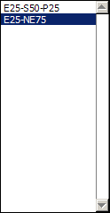
| Design Case Name |
- |
E25-NE75 |
25%
Emerg - > 75% NonEmerg |
|
|
|
for labeling output & reference to input
files |
|
|
|
|
|
|
|
|
| Starting Date for Simulation |
- |
01/00/00 |
|
|
|
|
|
|
0 =
use first date in input series |
|
|
|
|
|
|
|
|
|
| Ending Date for Simulation |
- |
01/00/00 |
|
|
|
|
|
|
0 =
use last date in input series |
|
|
|
|
|
|
|
|
|
| Starting Date for Output |
- |
01/00/00 |
|
|
|
|
|
|
0 =
use first date in simulation |
|
|
|
|
|
|
|
|
|
| Steps Per Day |
- |
4 |
Output Variable |
|
Units |
Value |
|
integration
steps per day (decrease to speed up simulation, increase if mass balance
errors are encountered) |
|
|
| Number of Iterations |
- |
2 |
Water Balance Error |
|
% |
0.0% |
|
number
of passes through the dataset to flush out initial values; 2 normally
sufficient to simulate system after growin period; |
| Output Averaging
Interval |
days |
7 |
Mass Balance Error |
|
% |
0.0% |
|
averaging
interval for time series output (e.g., 7 = weekly, 30 = monthly, 365 =
yearly) |
|
|
|
|
| Reservoir H2O Residence Time |
days |
0 |
Flow-Wtd Conc - With Bypass |
ppb |
27.8 |
|
rule
for regulating outflow from reservoir ( 0 = residence time not constrained ) |
|
|
|
|
|
| Max Inflow / Mean Inflow |
- |
0 |
Flow-Wtd Conc - Without Bypass |
ppb |
27.8 |
|
ratio
of maximum to mean daily inflow to treatment area; operating objective for
reservoir ( 0 = no peak flow control) |
|
| Max Reservoir Storage |
hm3 |
0 |
Geometric Mean Conc |
|
ppb |
15.4 |
|
maximum reservoir
volume (0 = no constraint) |
|
|
|
|
|
|
|
|
| Reservoir P Decay Rate |
1/yr/ppb |
0 |
95th Percentile Conc |
|
ppb |
42.4 |
|
second
order p removal rate in storage reservoir, nominal value ~ .15 1/yr/ppb; not
tested on south florida systems |
|
| Rainfall P Conc |
ppb |
10 |
Freq Cell Outflow > 10 ppb |
% |
68% |
|
rainfall
p concentration, wet deposition only (10 ppb assumed in calibrations) |
|
|
|
|
|
| Atmospheric P Load (Dry) |
mg/m2-yr |
20 |
Bypass Load |
|
% |
0.0% |
|
dry
deposition rate (20 mg/mg-yr assumed in calibrations) |
|
|
|
|
|
|
|
| Cell
Number --> |
|
1 |
2 |
3 |
4 |
5 |
6 |
|
|
|
|
|
|
|
|
|
|
|
|
|

|
- |
EM75 |
NE75 |
|
|
|
|
|
|
|
|
|
|
|
|
|
|
|
|
|
| Vegetation Type |
-------> |
EMERG |
NEWS |
|
|
|
|
|
assigns
pre-calibrated p cycling parameters based upon vegetation type; move cursor
to cell in range D:19-I19 & select parameter set from list boxl; select"none" to enter parameters directly in
rows 42-51 |
| Inflow Fraction |
- |
1 |
0 |
|
|
|
|
|
fraction
of basin flow entering cell ( 0 = receives inflow from upstream cell only) |
|
|
|
|
|
| Downstream Cell Number |
- |
2 |
0 |
|
|
|
|
|
cell
number receiving discharge from this cell ( 0 = outflow from treatment area);
cells must be in downstream order |
|
| Surface
Area |
km2 |
6.500 |
19.500 |
|
|
|
|
|
effective
treatment area (wet at normal operating level) |
|
|
|
|
|
|
|
| Mean Width of Flow Path |
km |
4.82 |
4.82 |
|
|
|
|
|
width = surface area / flow path length |
|
|
|
|
|
|
|
|
| Number of Tanks in Series |
- |
3 |
6 |
|
|
|
|
|
number of
cstr's in series (can include a
fraction) |
|
|
|
|
|
|
|
| Outflow Control Depth |
cm |
60 |
60 |
|
|
|
|
|
no outflow
below this water level (or constant depth) |
Zc |
|
|
|
|
|
|
| Outflow Coefficient - Exponent |
- |
3.5 |
3.5 |
|
|
|
|
|
for
computing outflow from depth (b) |
q / w
= a Z ^b for Z >= Zc |
typicallly ~ 3.5 |
|
|
|
| Outflow Coefficient - Intercept |
- |
0.8 |
0.8 |
|
|
|
|
|
flow/width
at water depth of 1 m (a), = 0 for constant depth |
|
typically 0.4 - 1.2 |
|
|
|
| Bypass
Depth |
cm |
140 |
140 |
|
|
|
|
|
depth at which bypass
begins ( 0 = no limit ) |
|
|
|
|
|
|
|
|
| Maximum Inflow |
hm3/day |
0 |
0 |
|
|
|
|
|
inflow capacity
(triggers bypass) ( 0 = no limit ) |
|
|
|
|
|
|
|
| Maximum Outflow |
hm3/day |
0 |
0 |
|
|
|
|
|
outflow
capacity (0 = no limit) |
|
|
|
|
|
|
|
|
|
| Inflow Seepage Rate |
(cm/d) / cm |
0 |
0 |
|
|
|
|
|
centimeters
per day per centimeter of head, reflects transmissivity of soils |
|
|
|
|
|
| Inflow Seepage Control Elev |
cm |
0 |
0 |
|
|
|
|
|
drives
inflow seepage rate, depth relative to mean ground surface elev |
|
|
|
|
|
| Inflow Seepage Conc |
ppb |
20 |
20 |
|
|
|
|
|
p conc of inflow seepage |
|
|
|
|
|
|
|
|
|
| Outflow Seepage Rate |
(cm/d) / cm |
0.008 |
0.008 |
|
|
|
|
|
centimeters
per day per centimeter of head, reflects transmissivity of soils |
|
|
|
|
|
| Outflow Seepage Control Elev |
cm |
0 |
0 |
|
|
|
|
|
drives
outflow seepage rate, relative to mean ground surface elev, can be < 0 |
|
|
|
|
|
| Max Outflow Seepage Conc |
ppb |
20 |
20 |
|
|
|
|
|
maximum
p conc of recycled & discharged seepage; seepage conc constrained to
<= water column conc |
|
|
| Seepage Recycle Fraction |
- |
0.5 |
0.5 |
|
|
|
|
|
fraction of
outflow seepage recycled to inflow of cell |
|
|
|
|
|
|
|
| Seepage Discharge
Fraction |
- |
0 |
0 |
|
|
|
|
|
fraction of
outflow seepage discharged to outlet of cell |
|
|
|
|
|
|
|
| Initial Water Column
Conc |
ppb |
30 |
30 |
|
|
|
|
|
initial water-column p concentration |
|
|
|
|
|
|
|
|
| Initial P Storage Per
Unit Area |
mg/m2 |
500 |
500 |
|
|
|
|
|
initial biomass p storage |
|
|
|
|
|
|
|
|
|
| Initial Water Column
Depth |
cm |
50 |
50 |
|
|
|
|
|
initial
water column depth relative to mean ground elevation |
|
|
|
|
|
|
|
| C0 = WC Conc at
0 g/m2 P Storage |
ppb |
4 |
12 |
|
|
|
|
|
water col umn
concentration @ storage = 0 mg/m2 |
assigned automatically based upon selected
vegetation type |
|
| C1 = WC Conc at 1 g/m2 P storage |
ppb |
22 |
22 |
|
|
|
|
|
water col umn
concentration @ storage =1000 mg/m2 |
" " |
|
|
|
|
|
|
| K = Net Settling Rate at
Steady State |
m/yr |
16 |
129 |
|
|
|
|
|
net settling rate in
steady state in K/C* model |
|
" " |
|
|
|
|
|
|
| Zx = Depth Scale Factor |
cm |
60 |
60 |
|
|
|
|
|
water
depth at maximum areal uptake |
|
" " |
|
|
|
|
|
|
| C0
- Periphyton |
ppb |
0 |
4 |
|
|
|
|
|
C0 for periphyton |
|
|
|
" " |
|
|
|
|
|
|
| C1
- Periphyton |
ppb |
0 |
22 |
|
|
|
|
|
C1 for
periphyton |
|
|
|
" " |
|
|
|
|
|
|
| K -
Periphyton |
1/yr |
0.00 |
23.80 |
|
|
|
|
|
K for periphyton |
|
|
|
" " |
|
|
|
|
|
|
| Zx
- Periphyton |
cm |
0 |
0 |
|
|
|
|
|
Zx for periphyton |
|
|
|
" " |
|
|
|
|
|
|
| Sm = Transition Storage Midpoint |
mg/m2 |
0 |
400 |
|
|
|
|
|
midpoint of transition from macrophyte to
periphyton |
" " |
|
|
|
|
|
|
| Sb = Transition Storage
Bandwidth |
mg/m2 |
0 |
80 |
|
|
|
|
|
bandwith of transition from macrophyte to
periphyton |
" " |
|
|
|
|
|
|
| |
|
|
|
|
|
|
|
|
|
|
|
|
|
|
|
|
|
|
|
|
| Output
Variables |
Units |
1 |
2 |
3 |
4 |
5 |
6 |
Overall |
Overall
= combined outflow from all cells, excluding bypass |
|
|
|
|
|
|
| Execution Time |
seconds/yr |
1.58 |
4.39 |
|
|
|
|
4.39 |
cumulative run
time in seconds per simulated year |
|
|
|
|
|
|
|
| Run Date |
- |
04/12/02 |
04/12/02 |
|
|
|
|
04/12/02 |
model run date |
|
|
|
|
|
|
|
|
|
|
| Starting Date for
Simulation |
- |
01/01/65 |
01/01/65 |
|
|
|
|
01/01/65 |
start simulation |
|
|
|
|
|
|
|
|
|
|
| Starting Date for Output |
- |
01/01/65 |
01/01/65 |
|
|
|
|
01/01/65 |
after startup period |
|
|
|
|
|
|
|
|
|
|
| Ending Date |
- |
12/31/95 |
12/31/95 |
|
|
|
|
12/31/95 |
last date |
|
|
|
|
|
|
|
|
|
|
|
| Output
Duration |
days |
11322 |
11322 |
|
|
|
|
11322 |
number of
simulated days (excluding startup
period) |
|
|
|
|
|
|
|
| Cell Label |
|
EM75 |
NE75 |
|
|
|
|
Total Outflow |
|
|
|
|
|
|
|
|
|
|
|
|
| Downstream Cell Label |
|
NE75 |
Outflow |
|
|
|
|
- |
|
|
|
|
|
|
|
|
|
|
|
|
| Surface Area |
km2 |
6.500 |
19.5 |
|
|
|
|
26.0 |
|
|
|
|
|
|
|
|
|
|
|
|
| Mean Water Load |
cm/d |
12.1 |
3.9 |
|
|
|
|
3.0 |
mean water load to treatment cell (flow / area) |
|
|
|
|
|
|
|
|
| Max Water Load |
cm/d |
122.6 |
41.7 |
|
|
|
|
30.6 |
maximum water load
to treatment cell (flow/area) |
|
|
|
|
|
|
|
| Inflow Volume |
hm3/yr |
288.2 |
281.3 |
|
|
|
|
288.2 |
external
inflow volume to treatment cell (excludes bypass) |
|
|
|
|
|
|
|
| Inflow Load |
kg/yr |
28833.0 |
21407.0 |
|
|
|
|
28832.1 |
external
inflow load to treatment cell (excludes bypass) |
|
|
|
|
|
|
|
| Inflow Conc |
ppb |
100.0 |
76.1 |
|
|
|
|
100.0 |
external inflow concentration |
|
|
|
|
|
|
|
|
|
| Treated Outflow Volume |
hm3/yr |
281.3 |
261.9 |
|
|
|
|
261.9 |
cell outflow +
discharged seepage (excludes bypass) |
|
|
|
|
|
|
|
| Treated Outflow Load |
kg/yr |
21407.9 |
7269.1 |
|
|
|
|
7269.1 |
cell outflow +
discharged seepage (excludes bypass) |
|
|
|
|
|
|
|
| Treated FWM Outflow Conc |
ppb |
76.1 |
27.8 |
|
|
|
|
27.8 |
cell outflow +
discharged seepage (excludes bypass) |
|
|
|
|
|
|
|
| Total Outflow Volume |
hm3/yr |
281.3 |
261.9 |
|
|
|
|
261.9 |
cell outflow + discharged
seepage + bypass |
|
|
|
|
|
|
|
|
| Total Outflow Load |
kg/yr |
21407.9 |
7270.1 |
|
|
|
|
7270.1 |
cell outflow + discharged
seepage + bypass |
|
|
|
|
|
|
|
|
| Total FWM Outflow Conc |
ppb |
76.1 |
27.8 |
|
|
|
|
27.8 |
treatment area outflow + bypass |
|
|
|
|
|
|
|
|
| Bypass Volume |
hm3/yr |
0.00 |
0.01 |
|
|
|
|
0.01 |
|
|
|
|
|
|
|
|
|
|
|
|
| Bypass Load |
kg/yr |
0.00 |
0.97 |
|
|
|
|
0.97 |
|
|
|
|
|
|
|
|
|
|
|
|
| Bypass Conc |
ppb |
0.0 |
74.9 |
|
|
|
|
74.9 |
|
|
|
|
|
|
|
|
|
|
|
|
| Bypass Load |
% |
0% |
0% |
|
|
|
|
0% |
percent of basin load bypassed around treatment
area |
|
|
|
|
|
|
|
| Surface Outflow Load
Reduc |
% |
25.8% |
66.0% |
|
|
|
|
74.8% |
between outflow from reservoir and outflow from
treatment area; ignores loads to groundwater |
|
|
|
| Outflow Geometric Mean - Daily |
ppb |
68.7 |
16.3 |
|
|
|
|
16.3 |
geometric mean of daily outflow concs on days
with flow > 0 |
|
|
|
|
|
|
| Outflow Geo Mean - Composites |
ppb |
69.2 |
15.4 |
|
|
|
|
15.4 |
geometric mean of n-day flow-weighted-means,
where n = averaging period for results |
|
|
|
|
| Frequency Outflow Conc
> 10 ppb |
% |
100% |
#DIV/0! |
|
|
|
|
68% |
percent
of composite intervals with flow-weighted-mean outflow conc > 10 ppb,
excluded bypass |
|
|
|
| 95th Percentile Outflow Conc |
ppb |
72.3 |
#NUM! |
|
|
|
|
42.4 |
95th percentile
of composite outflow concentrations |
|
|
|
|
|
|
|
| Mean Biomass P Storage |
mg/m2 |
3733 |
648 |
|
|
|
|
1419 |
|
|
|
|
|
|
|
|
|
|
|
|
| Max Reservoir Storage |
hm3 |
0.00 |
0.00 |
|
|
|
|
0.00 |
maximum volume of storage reservoir |
|
|
|
|
|
|
|
|
| Reservoir Load Reduction |
% |
#N/A |
#N/A |
|
|
|
|
#N/A |
phosphorus load reduction within reservoir |
|
|
|
|
|
|
|
|
| Mean Depth |
cm |
62.2 |
58.3 |
|
|
|
|
59.3 |
|
|
|
|
|
|
|
|
|
|
|
|
| Minimum Depth |
cm |
15.4 |
1.0 |
|
|
|
|
4.6 |
|
|
|
|
|
|
|
|
|
|
|
|
| Maximum Depth |
cm |
123.7 |
120.8 |
|
|
|
|
121.5 |
|
|
|
|
|
|
|
|
|
|
|
|
| Frequency Depth < 5 cm |
% |
0.0% |
0.0% |
|
|
|
|
0.0% |
|
|
|
|
|
|
|
|
|
|
|
|
| Flow/Width |
m2/day |
160 |
149 |
|
|
|
|
151.5 |
|
|
|
|
|
|
|
|
|
|
|
|
| Max 1 Yr Flow-Wtd Conc |
ppb |
#N/A |
#N/A |
|
|
|
|
42.8 |
rolling
average conc, computed for combined outflows only |
|
|
|
|
|
|
|
|
|
| Max 5 Yr Flow-Wtd Conc |
ppb |
#N/A |
#N/A |
|
|
|
|
31.7 |
"" |
|
|
|
|
|
|
|
|
|
|
|
| Max 1 Yr Geometric Mn
Conc |
ppb |
#N/A |
#N/A |
|
|
|
|
26.3 |
"" |
|
|
|
|
|
|
|
|
|
|
|
| Max 5 Yr Geometric Mn
Conc |
ppb |
#N/A |
#N/A |
|
|
|
|
17.2 |
"" |
|
|
|
|
|
|
|
|
|
|
|
| Depth Percentile vs. Calib Set |
% |
55% |
49% |
|
|
|
|
49% |
approximate
rank relative to calibration dataset, overall = last cell |
|
|
|
|
|
|
| Q/W Percentile vs. Calib Set |
% |
46% |
69% |
|
|
|
|
69% |
approximate
rank relative to calibration dataset, overall = last cell |
|
|
|
|
|
|
| Cin Percentile vs. Calib Set |
% |
82% |
83% |
|
|
|
|
82% |
approximate
rank relative to calibration dataset, overall = last cell |
|
|
|
|
|
|
| Cout Percentile vs. Calib Set |
% |
72% |
#N/A |
|
|
|
|
#N/A |
approximate
rank relative to calibration dataset, overall = last cell |
|
|
|
|
|
|
| Depth Range Flag |
- |
OK |
OK |
|
|
|
|
0.0 |
indicates depth out of calibration range |
|
|
|
|
|
|
|
|
| Q/W Range Flag |
- |
OK |
OK |
|
|
|
|
0.0 |
indicates flow/width
out of calibration range |
|
|
|
|
|
|
|
|
| Cin Range Flag |
- |
OK |
OK |
|
|
|
|
0.0 |
indicates inflow conc
out of calibration range |
|
|
|
|
|
|
|
|
| Cout Range Flag |
- |
OK |
|
|
|
|
|
0.0 |
indicates outflow
conc out of calibration range |
|
|
|
|
|
|
|
|
| Water Balance Error |
% |
0.00% |
0.00% |
|
|
|
|
0.00% |
increase
number of steps per day if this is large (e.g., > 1 %) |
|
|
|
|
|
|
| Mass Balance Error |
% |
-0.01% |
0.08% |
|
|
|
|
0.05% |
increase
number of steps per day if this is large
(e.g., >1%) |
|
|
|
|
|
|
| |
|
|
|
|
|
|
|
|
|
|
|
|
|
|
|
|
|
|
|
|
|
|
|
|
|
|
|
|
|
|
|
|
|
|
|
|
|
|
|
|
|